yamal现场部分图片
原作者:吴兆蕾
Observations from the visit 16th January 2017
Site investigations were carried out with Mike Murphy (STL) and Sergey Medviev (STL). Keith Proctor (Senior Field Engineer for Passive Protection), Robin Wade (Chartek Segment Manager), Lev Leviev (Key Account Manager AkzoNobel) and Valeriy Khramykh (Site Technical Service AkzoNobel)
Visual inspections were carried out on the following structures. Discussions regarding the observations were only conducted for structures where COOEC, CPOE, SOE and PJOE were responsible. There was an instruction not to discuss the observations from 715-PAU-001 from QMW. There were two distinctly difference failure modes for the Passive Fire Protection and Cold Spill Protection systems.

Passive Fire Protection
After a review of the findings by the joint investigation team, Mike Murphy (STL) summarised the findings as follows:
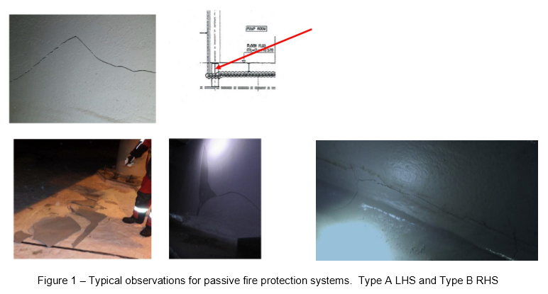
The majority (~90%) of defects on the modules were found on the webs of beams (Defect type A) – especially deep beams under modules – where surface cracking and signs of disbondment were observed (where in some cases the material had fallen off) (Figure 1). There were numerous modules affected – from all yards which have similar arrangement. The remaining (~10%) defects on modules were all localized and may be due to variety of different causes (Defect type B).
Further observations
Cracking was observed propagating from the connections of secondary and primary structural steel where there had only been “point contact” connection and the gap filled with Chartek. This was a common failure on all modules (Figure 2). Generally the Chartek was tightly adhering around the cracks for these areas.

Figure 2 – Cracking from infill on point connections
There were also signs of cracking from high stress points potentially due to movement. It was not possible to rule this out being a contributory factor for the disbondment between the first and second layers of Chartek for the “internal” structures accessible from ground level (large plate girders) (Figure 3). There was significant variation in the cracking observable at ground level between some modules from the same fabrication yard.

Figure 3 – Potential cracking due to movement on structures at ground level
Where there was disbondment from the first layer of Chartek the base layer was glossy in appearance and it was not uncommon to observe a mirror image of markings made on the first coat of Chartek prior to the application of the second coat (Figure 4 LHS). Generally flanges showed no or limited cracking whereas for the web areas cracking was more prevalent (Figure 4 RHS). In general the main circular hollow sections (CHS)
used for columns showed no failure. Cracking was apparent on some of the CHS legs where potentially undue stress had been applied. For the 100-PAR modules, there was a distinct difference observed in the performance of the lower levels (level B) in comparison with high levels in the pipe racks (levels F and G). For lower areas there was no visible sign of cracking observed however cracking was observed on the upper levels.

Figure 4 – Glossy under-layer with mirror image of markings appearing on back side of Chartek LHS. Cracking observable in the webs of beams RHS
For the top level of the pipe racks and SPP structures cracking tended to be hairline in nature particularly where the beams had a narrow web and it was difficult to control film thickness (Figure 5).

Figure 5 – Fine hairline cracking on smaller beams / columns with narrow webs
Observations from the visit 16th January 2017
Site investigations were carried out with Mike Murphy (STL) and Sergey Medviev (STL). Keith Proctor (Senior Field Engineer for Passive Protection), Robin Wade (Chartek Segment Manager), Lev Leviev (Key Account Manager AkzoNobel) and Valeriy Khramykh (Site Technical Service AkzoNobel)
Visual inspections were carried out on the following structures. Discussions regarding the observations were only conducted for structures where COOEC, CPOE, SOE and PJOE were responsible. There was an instruction not to discuss the observations from 715-PAU-001 from QMW. There were two distinctly difference failure modes for the Passive Fire Protection and Cold Spill Protection systems.
Passive Fire Protection
After a review of the findings by the joint investigation team, Mike Murphy (STL) summarised the findings as follows:
The majority (~90%) of defects on the modules were found on the webs of beams (Defect type A) – especially deep beams under modules – where surface cracking and signs of disbondment were observed (where in some cases the material had fallen off) (Figure 1). There were numerous modules affected – from all yards which have similar arrangement. The remaining (~10%) defects on modules were all localized and may be due to variety of different causes (Defect type B).
Further observations
Cracking was observed propagating from the connections of secondary and primary structural steel where there had only been “point contact” connection and the gap filled with Chartek. This was a common failure on all modules (Figure 2). Generally the Chartek was tightly adhering around the cracks for these areas.
Figure 2 – Cracking from infill on point connections
There were also signs of cracking from high stress points potentially due to movement. It was not possible to rule this out being a contributory factor for the disbondment between the first and second layers of Chartek for the “internal” structures accessible from ground level (large plate girders) (Figure 3). There was significant variation in the cracking observable at ground level between some modules from the same fabrication yard.
Figure 3 – Potential cracking due to movement on structures at ground level
Where there was disbondment from the first layer of Chartek the base layer was glossy in appearance and it was not uncommon to observe a mirror image of markings made on the first coat of Chartek prior to the application of the second coat (Figure 4 LHS). Generally flanges showed no or limited cracking whereas for the web areas cracking was more prevalent (Figure 4 RHS). In general the main circular hollow sections (CHS)
used for columns showed no failure. Cracking was apparent on some of the CHS legs where potentially undue stress had been applied. For the 100-PAR modules, there was a distinct difference observed in the performance of the lower levels (level B) in comparison with high levels in the pipe racks (levels F and G). For lower areas there was no visible sign of cracking observed however cracking was observed on the upper levels.
Figure 4 – Glossy under-layer with mirror image of markings appearing on back side of Chartek LHS. Cracking observable in the webs of beams RHS
For the top level of the pipe racks and SPP structures cracking tended to be hairline in nature particularly where the beams had a narrow web and it was difficult to control film thickness (Figure 5).
Figure 5 – Fine hairline cracking on smaller beams / columns with narrow webs
点赞0觉得这条内容有用,点个赞
标签:本帖暂无标签 —— 标题里没有可识别的行业关键词
评分:绿叶 +3登录后评分